4.9 Equipment settings
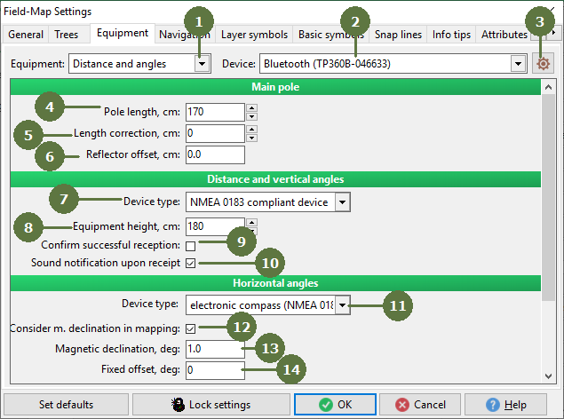
- Equipment
List of equipment supported by Field-Map. Choose one to specify its parameters.
- Device
Choose a Bluetooth or serial port used for communication with a particular device.
- Settings for Bluetooth or COM
These parameters need to be set to meet the requirements of a particular device.
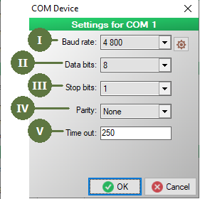
- Data rate in bits per second
- Number of data bits in each character
- Stop bits sent at the end of every character
- The parity bit in each character
- A specified period of time that will be allowed to elapse in a system before a specified event is to take place
Note: settings for Bluetooth, see chapter Bluetooth connection
- Main pole length
The main pole is the assistant’s range pole used for most measurements. Because we are always interested in the altitude of terrain, not in altitude of the reflector, it is necessary to define the height of main pole that will then be subtracted.
- Main pole length correction
This option allows user to set any difference for the length of the main pole (e.g. industrial telescopic poles are usually manufactured for the geometricians and there is presumption of using special extension, in fact the length of pole is shorter than the scale on the pole shows).
- Main pole reflector offset
Distances measured by laser are always measured to the surface of the reflector, but this surface is actually shifted a bit towards the laser and this shift distorts the measurement. The value of the entered number will be added to the distance.
- Distance and vertical angles - device type
Choose equipment that you use for measuring distance and horizontal angles.
- Equipment height
This is the same as with main pole length. The equipment has a certain offset from the ground (measured from main mounting knob) and this must be entered in order to calculate the real altitude.
- Confirm successful reception
Check this box if using wireless technology (radio waves) for laser rangefinder and computer radio communication. Field-Map automatically confirms successful communication.
- Sound notification upon receipt
Check this box for listen a audio notification upon receipt.
- Horizontal angles - device type
Choose equipment that you use for measuring horizontal angles.
- Consider m. declination in mapping
This setting is active only when compass is selected as a device type. If this option is checked the value of magnetic declination is used to correct azimuth values received from the compass. Otherwise the value of magnetic declination for the plot is stored just for informational purpose.
- Magnetic declination
This setting is active only when compass is selected as a device type. Value of magnetic declination is specific for each plot and this field is just an overview of attribute Magnetic_decl_deg in plot layer. Therefore setting the value of magnetic declination in this dialog sets the value Magnetic_decl_deg in plot layer and vice versa. For some electronic compasses there is a possibility to set magnetic declination directly in the device. This will make the device send already corrected azimuth values.
We strongly recommend to keep magnetic declination set to 0 in the device and use this software setting instead (together with checking the option “consider m. declination in mapping”). The azimuth correction then works for each plot and device automatically without necessity to adjust the hardware setting of device where this task can be easily forgotten. In case you use mechanical compass you have no other choice than to use the software setting.
- Fixed offset
This setting is active only when compass is selected as a device type. Value of fixed offset allows you to eliminate some constant error of your compass. A measured azimuth value is corrected by magnetic declination (if enabled) and then this value is added to the result.
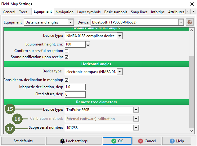
- Remote tree diameters - device type
Choose a method that you use for measurement of remote diameters. Impuls + scope (IFER) uses a calculation function built into Field-Map while Criterion (LTI) uses function provided by the external device.
- Calibration method
This setting is active only when Impuls + scope (IFER) is selected as device type. It allows you to calibrate laser with scope either by using Internal (hardware) or External (software) method. When using internal calibration the scope is mechanically calibrated for precise measurement by manufacturer. Newly manufactured scopes are calibrated by setting calibration parameters in Field-Map so all you need to do is just to choose the correct scope you are going to use from the list.
- Scope serial number
This setting is active only when External (software) calibration method is selected. To calibrate your scope just select the serial number of it from the list of all manufactured scopes. If your scope is not listed please contact IFER.
GNSS
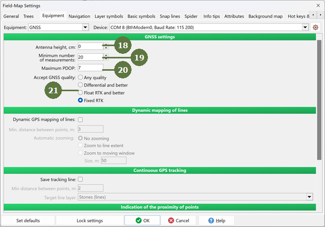
- Antenna height
GPS measured altitude refers to the GPS antenna and we therefore need to know the height of antenna to be able to calculate the altitude of the point on the ground.
- Minimum number of measurements
The GPS sends measurements in time intervals. Field-Map accepts measured positions after a defined number of measurements.
- Maximum PDOP
A greater value means less reliable mutual position of satellites and will result in an inaccurate position measurement.
- Accept GNSS quality
Field-Map accepts only corrected signal using various services.
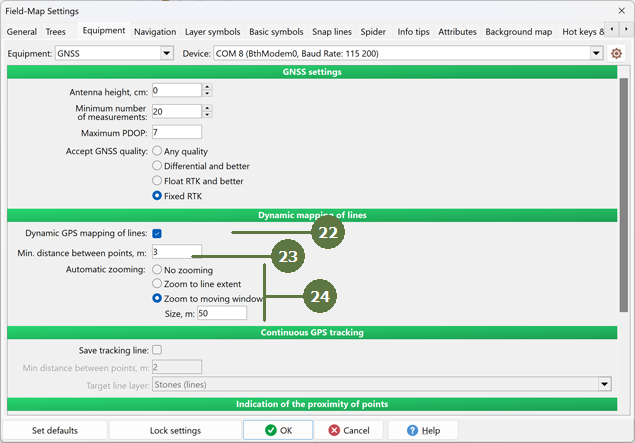
- Dynamic GPS mapping of lines
This option allows user to map lines using GPS and simultaneously describe attributes of the line. Dynamic mapping with GPS works with 1-second measurement while static mapping always calculates average position from the number of measurement specified in Minimum number of measurement textbox.
- Min. distance between points
User can specify what will be the distance between the vertexes of mapped lines.
- Automatic zooming
Automatic zoom defines how the zoom will behave when the line is mapped. No zooming means that zoom remains the same, as it was when line mapping started. Zoom to line extent means that Field-Map continuously change the zoom depending on extend of mapped line. Zoom to moving window means that particular area defined in "Size" text box remains visible and the window is moving that the last segment of line is always visible.
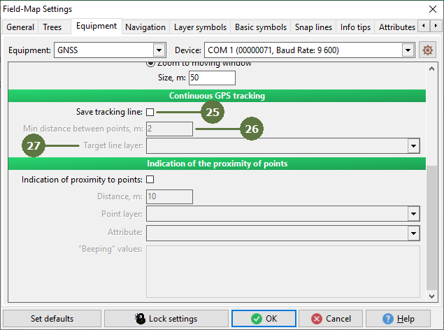
- Continuous GPS tracking - Save tracking line
If active, FMDC continuously stores a tracking line to a selected layer of line type. The tracking line is created using incoming data from GPS device. The creation of a tracking line does not need to be activated - when this feature is enabled and a GPS device connected, the tracking line will be automatically built.
- Min. distance between points
Enables to set the minimal distance between points of a tracking line - a new point is inserted into the line only if its distance from the last point in the line is at least equal this value.
- Target line layer
A layer of line type to store a tracking line.
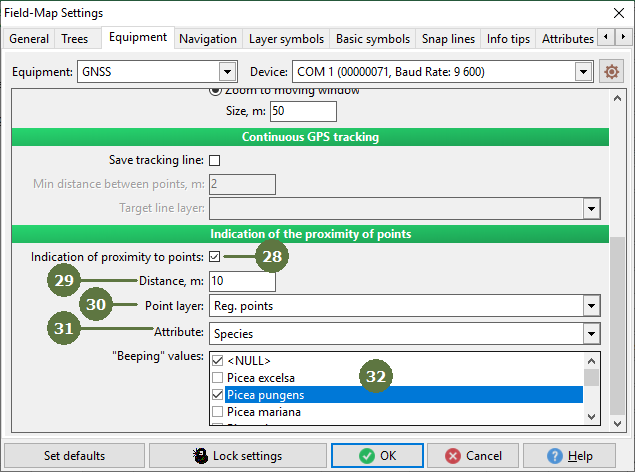
- Indication of the proximity to points
This function can be used in the field as a proximity alert which acoustically indicates when a user gets close to a point from a particular layer.
- Distance
Sets the distance from a point at which FMDC starts to beep.
- Point layer
Selected layer of point type for which the proximity alert is active.
- Attribute
Name of an attribute which is used to activate/deactivate proximity alert for each point in the target point layer. This attribute needs to be of lookup type and a user can define for which value(s) the proximity alert should be active. If the user gets closer than specified distance to the particular point and the value of this attribute of that point enables the proximity alert, FMDC starts to make a sound. Then the user can stop the alarm simply by setting this attribute to some value for which the alarm is disabled.
- “Beeping” values
List of all possible values of the attribute described above. Check the values for which the proximity alert should be active.
Electronic calliper
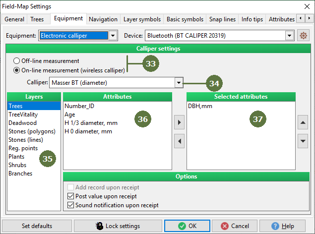
- Off-line or On-line measurement
Field-Map supports both modes of calliper measurement. Off-line mode means that tree diameters data from the entire plot is stored in the calliper memory and loaded to the field computer via serial port after finishing the plot measurement. On-line mode means that wireless calliper sends each measurement on-line.
- Calliper
Select type of the on-line calliper.
- Layers
List of all available map and data layers.
- Attributes
List of all attributes from layer chosen above which can be selected to be loaded from wireless calliper. The attributes can be moved to list of selected attributes by clicking arrow button.
- Selected attributes
Ordered list of attributes from selected layer which are already selected to be loaded from wireless calliper. The selected attribute can be removed from the list by clicking arrow button on the left side of the list. Note that you can change the order in which the attributes will be loaded by selecting an attribute and clicking arrow buttons on the right side of the list.
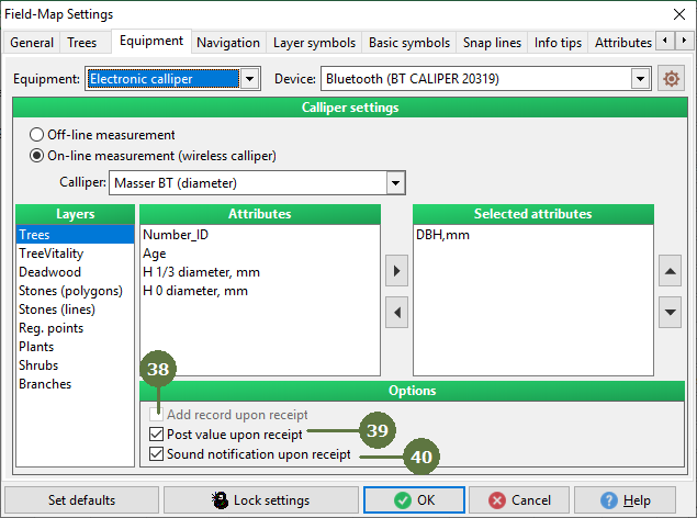
- Add record upon receipt
This option is available only for data layers. When active the new record is added to the layer automatically every time first of the attributes selected for loading from wireless calliper is received.
- Post value upon receipt
When this option is active the values received from wireless calliper are stored to the corresponding attributes without the need of manual confirmation. If inactive the queue of received values is displayed in separate sub window and the assignment of every value to its corresponding attribute has to be confirmed by clicking “Post” button.
- Sound notification upon receipt
Check this box for listen a audio notification upon receipt.